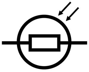
Open main menu

Light Dependent Resistor

Revision as of 18:22, 28 February 2019 by NRJC (talk | contribs)

Key Stage 4

Meaning

The symbol for a light dependent resistor.

A light dependent resistor (LDR) is a resistor which changes resistance depending on the intensity of light that it is exposed to.

About Light Dependent Resistors

Light dependent resistors decrease resistance as the intensity of light increases.
A light dependent resistor can be used to control the current passing through a circuit. If the potential difference is constant then the current decreases as the light intensity decreases.
A light dependent resistor can be used to control the potential difference of another component in series with it. If the light intensity on the light dependent resistor is decreased then the potential difference across other components will decrease.
Light dependent resistors can be used in security lights and street lamps which activate depending on how dark it is.

IV Graph

LDRPotentialDivider2.png
LDRPotentialDivider1.png
In this circuit diagram the light intensity is low, which causes the resistance of the LDR to be high. As a result the potential difference across the lamp will be high (5.9V) and the current through the lamp will be large. So in dim light the lamp will remain lit. In this circuit diagram the light intensity is high, which causes the resistance of the LDR to be low. As a result the potential difference across the lamp will be low (0.1V) and the current through the lamp will be low. So in bright light the lamp will remain unlit.

IV Graph

IVGraphLDR.png

Description

The IV Graph for a light dependent resistor shows that:

Explanation

The resistance of an LDR increases as the light intensity decreases.

Obtaining the IV Graph

LDRIVGraphCircuit.png
  1. Connect an ammeter in series with the LDR to measure current through the LDR.
  2. Connect a voltmeter in parallel with the LDR to measure the potential difference across it.
  3. Use a variable resistor in series with the LDR to vary the potential difference across the LDR.
  4. Cover the LDR so that very little light reaches its surface.
  5. Start with a potential difference of zero and increase the potential difference by an interval of 0.2V up to 2V.
  6. Recording the reading on the voltmeter and ammeter.
  7. Reverse the connections on the battery and repeat steps 4 and 5 to find the I-V relationship for negative potential difference and current.
  8. Repeat steps 5-7 while shining a constant bright light on the LDR