Difference between revisions of "Circuit Diagram"
| Line 14: | Line 14: | ||
|[[File:CircuitDiagramSeries1Cell1Bulb.png|center|200px]] | |[[File:CircuitDiagramSeries1Cell1Bulb.png|center|200px]] | ||
|[[File:CircuitDiagramSeries1Cell2Bulb.png|center|200px]] | |[[File:CircuitDiagramSeries1Cell2Bulb.png|center|200px]] | ||
| + | |- | ||
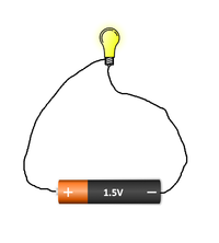
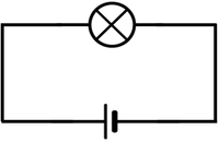
| + | | style="height:20px; width:200px; text-align:center;" |The circuit diagram shows a cell connected to one bulb. | ||
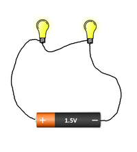
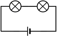
| + | | style="height:20px; width:200px; text-align:center;" |The circuit diagram shows a cell connected to two bulbs. | ||
| + | |||
|} | |} | ||
Revision as of 13:29, 1 September 2018
Key Stage 2
Meaning
A circuit diagram is a simple diagram using circuit symbols that are the same everywhere in the world.
About Circuit Diagrams
- Circuit diagrams are drawn so that anyone in the world can build the same circuit.
- Circuit diagrams use symbols instead of drawings because components might look different in different places.
| The circuit diagram shows a cell connected to one bulb. | The circuit diagram shows a cell connected to two bulbs. |


