Difference between revisions of "Thermistor"
(→Description) |
(→IV Graph) |
||
| Line 22: | Line 22: | ||
====Explanation==== | ====Explanation==== | ||
: The [[Electrical Resistance|resistance]] of an 'NTC' [[thermistor]] increases as the [[temperature]] decreases. | : The [[Electrical Resistance|resistance]] of an 'NTC' [[thermistor]] increases as the [[temperature]] decreases. | ||
| + | |||
| + | ====Obtaining the IV Graph==== | ||
| + | {| class="wikitable" | ||
| + | |- | ||
| + | |[[File:ThermistorIVGraphCircuit.png|center|300px]] | ||
| + | | style="height:20px; width:300px; text-align:left;" | | ||
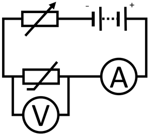
| + | #Connect an [[ammeter]] in [[Series Circuit|series]] with the [[thermistor]] to measure [[Electrical Current|current]] through the [[thermistor]]. | ||
| + | #Connect a [[voltmeter]] in [[Parallel Circuit|parallel]] with the [[thermistor]] to measure the [[Potential Difference|potential difference]] across it. | ||
| + | #Use a [[Variable Resistor|variable resistor]] in [[Series Circuit|series]] with the [[thermistor]] to vary the [[Potential Difference|potential difference]] across the [[resistor]]. | ||
| + | #Place the [[thermistor]] in a [[beaker]] of cold [[water]] around 5°C. | ||
| + | #Start with a [[Potential Difference|potential difference]] of zero and increase the [[Potential Difference|potential difference]] by an interval of 0.2V up to 2V. | ||
| + | #Recording the reading on the [[voltmeter]] and [[ammeter]]. | ||
| + | #Reverse the connections on the [[battery]] and repeat steps 4 and 5 to find the I-V relationship for negative [[Potential Difference|potential difference]] and [[Electrical Current|current]]. | ||
| + | #Repeat steps 5-7 with the [[thermistor]] in a [[beaker]] of hot [[water]] around 40°C. | ||
| + | |} | ||
Revision as of 18:20, 28 February 2019
Contents
Key Stage 4
Meaning
A thermistor is a resistor which changes resistance depending on the temperature.
About Thermistors
- 'NTC' thermistors decrease resistance as the temperature increases. (NTC = Negative Temperature Coefficient.)
- A thermistor can be used to control the current passing through a circuit. If the potential difference is constant then the current decreases as temperature decreases.
- A thermistor can be used to control the potential difference of another component in series with it. If the temperature is decreased then the potential difference across other components will decrease.
- Thermistors can be used temperature sensors.
IV Graph
Description
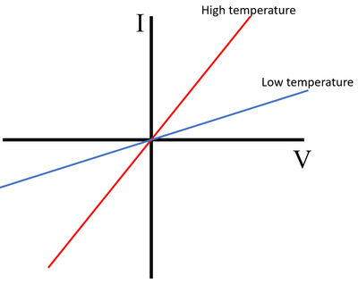
The IV Graph for an 'NTC' thermistor shows that:
- At a high temperature the current increases rapidly with the potential difference
- At a low temperature the current increases slowly with the potential difference.
Explanation
- The resistance of an 'NTC' thermistor increases as the temperature decreases.
Obtaining the IV Graph
|


