Difference between revisions of "Circuit Diagram"
(Created page with "==Key Stage 2== ===Meaning=== A '''circuit diagram''' is a simple diagram using circuit symbols that are the same everywhere in the world. ===About Cir...") |
|||
| (10 intermediate revisions by the same user not shown) | |||
| Line 6: | Line 6: | ||
: [[Circuit Diagram|Circuit diagrams]] are drawn so that anyone in the world can build the same [[circuit]]. | : [[Circuit Diagram|Circuit diagrams]] are drawn so that anyone in the world can build the same [[circuit]]. | ||
: [[Circuit Diagram|Circuit diagrams]] use [[Circuit Symbol|symbols]] instead of drawings because [[Electrical Component|components]] might look different in different places. | : [[Circuit Diagram|Circuit diagrams]] use [[Circuit Symbol|symbols]] instead of drawings because [[Electrical Component|components]] might look different in different places. | ||
| + | |||
| + | {| class="wikitable" | ||
| + | |- | ||
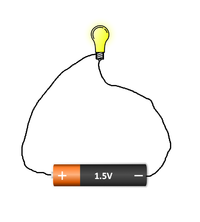
| + | |[[File:SeriesCircuitSketch1.png|center|200px]] | ||
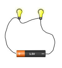
| + | |[[File:SeriesCircuitSketch2.png|center|200px]] | ||
| + | |- | ||
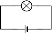
| + | |[[File:CircuitDiagramSeries1Cell1Bulb.png|center|200px]] | ||
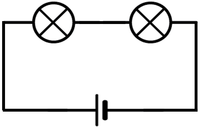
| + | |[[File:CircuitDiagramSeries1Cell2Bulb.png|center|200px]] | ||
| + | |- | ||
| + | | style="height:20px; width:200px; text-align:center;" |The circuit diagram shows a cell connected to one bulb. | ||
| + | | style="height:20px; width:200px; text-align:center;" |The circuit diagram shows a cell connected to two bulbs. | ||
| + | |||
| + | |} | ||
| + | |||
| + | ==Key Stage 3== | ||
| + | ===Meaning=== | ||
| + | A '''circuit diagram''' is a simple [[diagram]] used to show how a [[circuit]] is put together. | ||
| + | ===About Circuit Diagrams=== | ||
| + | : [[Circuit Diagram|Circuit diagrams]] are drawn so that anyone in the world can build the same [[circuit]]. | ||
| + | : [[Circuit Diagram|Circuit diagrams]] use [[Circuit Symbol|symbols]] instead of drawings because [[Electrical Component|components]] might look different in different places. | ||
| + | |||
| + | {| class="wikitable" | ||
| + | |- | ||
| + | |[[File:CircuitCellBulbAmmeterSeries.png|center|200px]] | ||
| + | |[[File:CircuitCellBulbVoltmeterParallel.png|center|200px]] | ||
| + | |[[File:CircuitCellBulbBulbParallel.png|center|200px]] | ||
| + | |- | ||
| + | |[[File:CircuitDiagramCellBulbAmmeterSeries.png|center|200px]] | ||
| + | |[[File:CircuitDiagramCellBulbVoltmeterParallel.png|center|200px]] | ||
| + | |[[File:CircuitDiagramCellBulbBulbParallel.png|center|200px]] | ||
| + | |} | ||
| + | |||
| + | {| class="wikitable" | ||
| + | |- | ||
| + | |[[File:CircuitCellMotorResistorSeries.png|center|200px]] | ||
| + | |[[File:CircuitCellMotorBulbParallel.png|center|200px]] | ||
| + | |[[File:CircuitCellMotorResistorBulbSeries.png|center|200px]] | ||
| + | |- | ||
| + | |[[File:CircuitDiagramCellMotorResistorSeries.png|center|200px]] | ||
| + | |[[File:CircuitDiagramCellMotorBulbParallel.png|center|200px]] | ||
| + | |[[File:CircuitDiagramCellMotorResistorBulbSeries.png|center|200px]] | ||
| + | |} | ||
| + | |||
| + | ==Key Stage 4== | ||
| + | ===Meaning=== | ||
| + | A '''circuit diagram''' is a simple [[diagram]] used to show the arrangement of [[Electrical Component|components]] in a [[circuit]]. | ||
| + | |||
| + | ===About Circuit Diagrams=== | ||
| + | : [[Circuit Diagram|Circuit diagrams]] are drawn so that anyone in the world can build the same [[circuit]]. | ||
| + | : [[Circuit Diagram|Circuit diagrams]] use [[Circuit Symbol|symbols]] instead of drawings because [[Electrical Component|components]] might look different in different places. | ||
| + | |||
| + | ===Examples=== | ||
| + | {| class="wikitable" | ||
| + | |- | ||
| + | |[[File:DiodeIVGraphCircuit.png|center|200px]] | ||
| + | |[[File:LDRPotentialDivider2.png|center|200px]] | ||
| + | |[[File:ResistanceWireCircuit2.png|center|200px]] | ||
| + | |- | ||
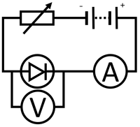
| + | | style="height:20px; width:200px; text-align:center;" |This '''circuit diagram''' shows a [[circuit]] which can be used to plot the [[IV Graph]] for a [[diode]]. | ||
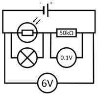
| + | | style="height:20px; width:200px; text-align:center;" |This '''circuit diagram''' shows a [[circuit]] which can be used to activate a [[Electrical Bulb|lamp]] when it is dark. | ||
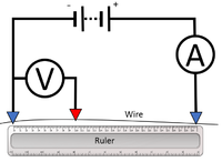
| + | | style="height:20px; width:200px; text-align:center;" |This '''circuit diagram''' shows a [[circuit]] which can be used to find the [[Electrical Resistance|resistance]] of a [[wire]]. | ||
| + | |} | ||
Latest revision as of 18:04, 28 February 2019
Contents
Key Stage 2
Meaning
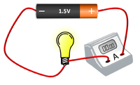
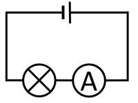
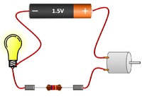
A circuit diagram is a simple diagram using circuit symbols that are the same everywhere in the world.
About Circuit Diagrams
- Circuit diagrams are drawn so that anyone in the world can build the same circuit.
- Circuit diagrams use symbols instead of drawings because components might look different in different places.
| The circuit diagram shows a cell connected to one bulb. | The circuit diagram shows a cell connected to two bulbs. |
Key Stage 3
Meaning
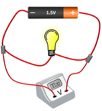
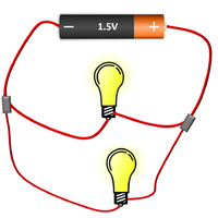
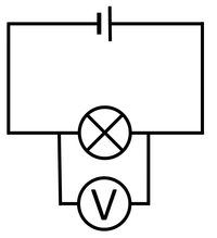
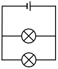
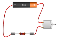
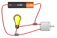
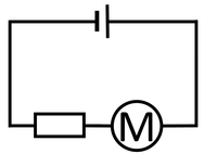
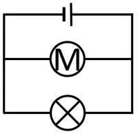
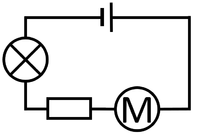
A circuit diagram is a simple diagram used to show how a circuit is put together.
About Circuit Diagrams
- Circuit diagrams are drawn so that anyone in the world can build the same circuit.
- Circuit diagrams use symbols instead of drawings because components might look different in different places.
Key Stage 4
Meaning
A circuit diagram is a simple diagram used to show the arrangement of components in a circuit.
About Circuit Diagrams
- Circuit diagrams are drawn so that anyone in the world can build the same circuit.
- Circuit diagrams use symbols instead of drawings because components might look different in different places.
Examples
| This circuit diagram shows a circuit which can be used to plot the IV Graph for a diode. | This circuit diagram shows a circuit which can be used to activate a lamp when it is dark. | This circuit diagram shows a circuit which can be used to find the resistance of a wire. |
